
TM 11-5985-362-13
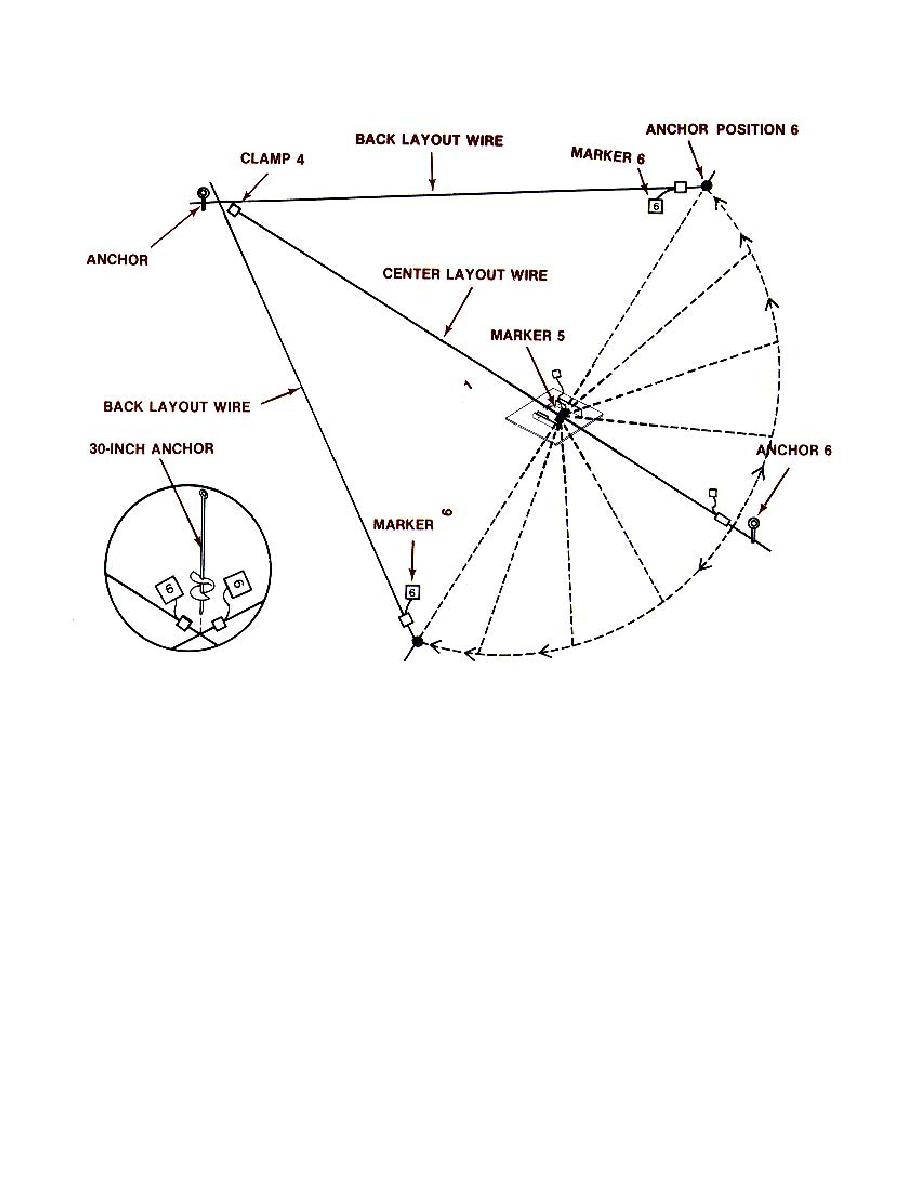
Third crewmember takes the end of CENTER LAYOUT WIRE (at SLEEVE with marker tag 6), one 30 inch anchor
and walks counterclockwise to SLEEVE with marker tag 6 on BACK LAYOUT WIRE.
Holding both SLEEVES together, hand tension wires to form a triangle.
Insert point of anchor (at intersection of SLEEVES) into ground to mark location for LEFT SIDE ANCHOR (6).
Leave 30 inch anchor, proceed clockwise with end of CENTER LAYOUT WIRE (SLEEVE with marker tag 6) and pick
up other 30 inch anchor.
Walk to SLEEVE with marker tag 6 on BACK LAYOUT WIRE.
Holding both SLEEVES together, hand tension wires to form a triangle.
Insert point of anchor (at intersection of SLEEVES) into ground to mark location for RIGHT SIDE ANCHOR (6).
Leave 30 inch anchor, return CENTER LAYOUT WIRE to its original position (straight line between ANCHOR 1 and
6).
Obtain shovel/pick and antenna coupler bar from antenna transit cases and install the four 30 inch anchors as
follows:
2-20

 Previous Page
