
TM 11-5985-362-13
NOTE
If the antenna curtain was rotated to its original position some of the following steps
will already have been done.
Shutdown transmitter and tag transmitter "Out of Service".
Disconnect transmitter coaxial cable from ANTENNA COUPLER.
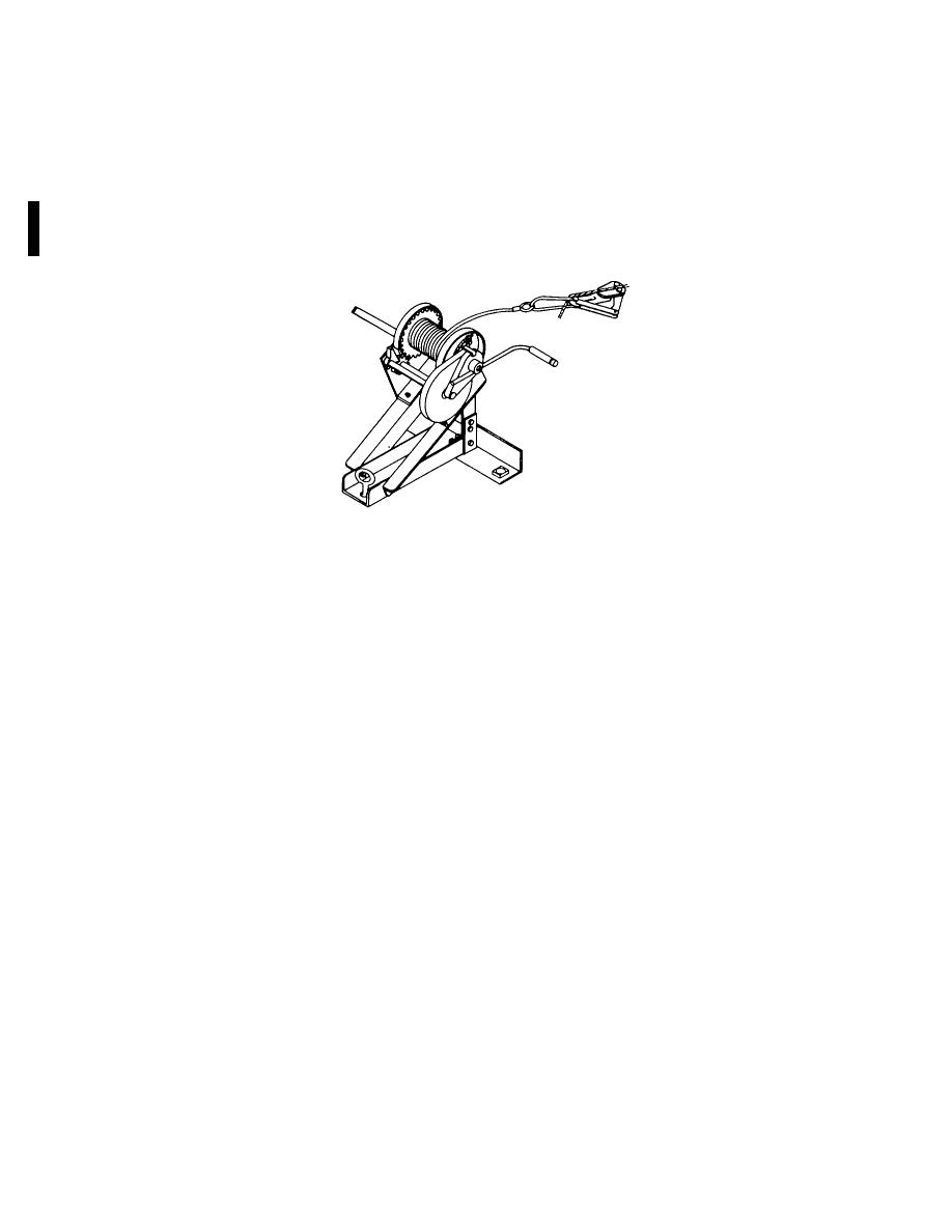
From antenna transit case, obtain TOWER WINCH ASSEMBLY, hammer and two TOWER BASE PINS and
carry to ANCHOR 6A. Position winch base slot over anchor eye. Rotate winch to directly face antenna
tower with anchor eye cross-wise 900 to slot.
Using hammer, drive two TOWER BASE PINS into the ground until pin heads are securely against the top of
base.
Attach wire/cable gripper of TOWER WINCH to STAINLESS STEEL TOWER GUY. (attach just above
MARKER SLEEVE on guy).
Tension STAINLESS STEEL TOWER GUY and remove CABLE CLAMP from ANCHOR 6.
Disconnect the VERTICAL FEEDLINE from the top of ANTENNA COUPLER.
Loosen and disconnect the VERTICAL FEEDLINE and VERTICAL CATENARY from their pound-in
Disconnect the CENTER LAYOUT WIRE from ANTENNA COUPLER MOUNTING BAR.
Remove ANTENNA COUPLER, ANTENNA COUPLER BAR and pound-in ANCHORS of VERTICAL
CATENARY, FEEDLINE.
At antenna transit case, obtain empty REEL NO. 4 and return to VERTICAL RADIATOR.
Disconnect VERTICAL RADIATOR from MAIN FEEDLINE and wind onto REEL NO. 4.
Move REEL NO. 4 behind ANCHOR 6.
If removed since installation, attach GIN POLE to TOWER/GIN POLE BASE using three TOWER SPLICES.
Disconnect top right and left ROPE TOWER GUYS from their respective ANCHOR (6).
Disconnect right and left LOWER TOWER GUYS from their respective ANCHOR (6).
Station three crewmembers as follows:
(a) One at TOWER WINCH ASSEMBLY
(b) One at end of LEFT MIDDLE TOWER GUY
(c) One at end of RIGHT MIDDLE TOWER GUY
Disconnect RIGHT and LEFT MIDDLE TOWER GUYS from their ANCHOR (6) and hand tension to maintain
TOWER in a vertical position.
2-60

 Previous Page
