TM 11-5985-355-13
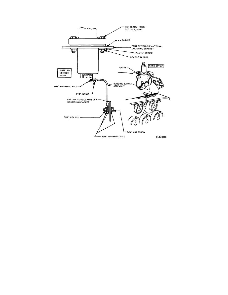
Figure 2-4. Typical bonding jumper setups.
Section II. OPERATING INSTRUCTIONS
compatible
receiver-transmitter)
which
positions
2-4. Operator's Control and Connectors
frequency selector switch S1. Cable assembly CX-
(fig. 2-5)
13055/GRC adapts radio control cable to connector J2.
Frequency selector switch S1 is used for manual
2-5. Operating Procedure
selection of the correct tuning components for the 10
frequency band segments.
This switch operates
(fig. 2-5)
automatically when the AS-2731/GRC is connected to a
a. The AS-2731/GRC is automatically tuned to the
compatible receiver-transmitter which contains automatic
operating frequency band segment when used with a
antenna tuning facilities. Connector J1 connects the AS-
compatible receiver-transmitter. When used with radios
2731/GRC to a receiver-transmitter rf out-put circuit.
not provided with the automatic tuning function, or when
Connector J2 provides coding input information (from a
radio automatic tuning circuit is defective, the AS-2731/
2-5


 Previous Page
