
TM 11-5821-284-34
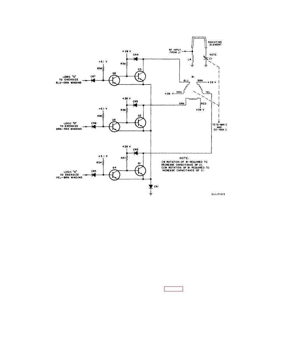
Figure 2-8. Servo motor and motor control logic, simplified schematic diagram.
base of Q15. Transistor Q15 conducts supplying a logic
the ferrite core produces a small variable series
"O" to CR19 and causing the coupler to tune toward
inductance used for fine tuning the antenna.
minimum capacitance of the antenna tuning capacitor
thereby increasing the resonant frequency of the
2-15.
Power Sources Analysis
(Fo 6-2, 6-3)
The power required by the antenna is a +28-volt dc
2-14. Antenna Circuit Analysis (FO 6-2, 6-3)
source This +28-volt dc source controls three voltage
The antenna is a vertically polarized, folded monopole,
dividers for the operation of the antenna. A +5.1-volt dc
divider is used for logic functions, a +6.2-volt dc divider is
matched to the impedance of a 50-ohm transmission
used for a signal reference in the operational amplifier
line.
ARI, and a + 13.7-volt dc divider is used for gatlng
a. The antenna circuit is tuned by varying
functions.
series capacitance. Shunt inductor L4 matches the
antenna impedance with the impedance of a 50-ohm
transmission line when the antenna circuit is at
2-16.
Tuning Indicator Drive Analysis
b. A small ferrite core placed around the
The tuning indicator drive supplies square-wave output
antenna uses the magnetic field generated by L1 and L2
pulses (nearly identical to pulses supplied
to change permeability. The change in permeability of
2-10

 Previous Page
