
TM 11-5821-284-34
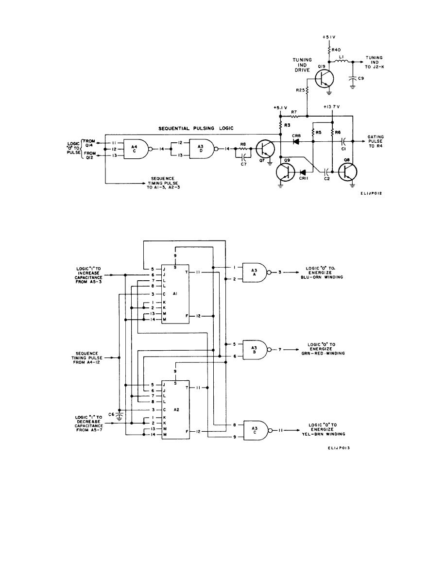
Figure 2-6. Sequential pulsing logic, simplified schematic diagram.
Figure 2-7. Servo motor sequencing logic, simplified schematic diagram.
d. Servo Motor Sequencing Logic, Truth Table
c. When a logic "O" is supplied by A5B-7 and
for Cw Rotation (Decrease Capacitance).
a logic "1" is supplied by A5A3, a counterclockwise
rotation of the servo motor is initiated. Refer to e and f
(below) for the servo motor sequencing logic truth tables
for counter clockwise rotation.
2-7

 Previous Page
