
TM 11-5821-284-34
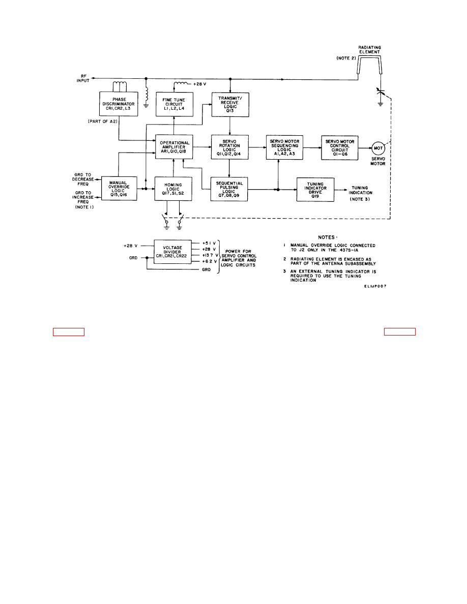
Figure 2-1. Antenna AS-285/ARC, vhf/fm blade type, functional block diagram analysis.
b. When the output from AR1 changes above
2-5.
Operational Amplifier Analysis
or below the threshold of CR9 or CR10, (fig. 2-5), servo
rotation logic is turned on, engaging the sequential
Operational amplifier AR1 amplifies input signals from
pulsing logic which, in turn, pro-vides a gating pulse to
the phase discriminator, homing logic circuit, and manual
Q18.
override circuit; provides a voltage level for driving servo
c. When field-effect transistor Q18 is gated, it
logic circuits; pro-vides a voltage output for fine tuning
supplies a portion of the dc voltage output as a dc
the antenna; and contains a gating circuit to control the
voltage feedback to the input of AR1 causing the output
speed of the servo motor proportional to the operational
to be pulsed in the direction of the in-put reference
amplifier input up to a maximum servo motor speed of
voltage (+6.2 volts dc). When Q18 is gated on, the
1250 rpm. a The operational amplifier circuit operates
amplifier circuit is limited to a gain of approximately six
as a linear voltage input to output pulse rate converter.
which is the ratio of R22 to R9.
Operational amplifier AR1 is a high-gain differential dc
d. With a gating pulse supplied, Q18 is a short
amplifier. With an input applied between AR1-3 and
circuit across C4 and the output voltage level is reduced
AR1-2, the amplifier produces a voltage gain of
(upward or downward) toward the +6.2-volt dc reference
approximately 1000 with output polarity inverse of the
level. The output is returned to a voltage level six times
input polarity. By means of a degenerative feedback
the input signal level and,
loop consisting of (C4 and R22) and input resistor R9 the
output of AR1 is controlled to a linear rate of increase.
The high gain of AR1 and the control by C4, R22, and R9
produces a very sensitive amplifier, capable of sensing
very low-level input signals.
2-3

 Previous Page
