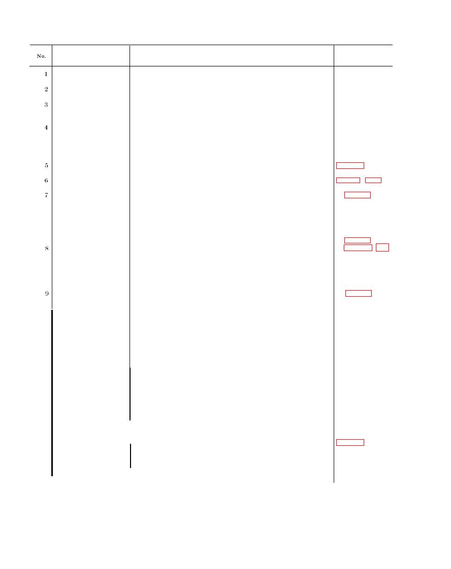
TM 11-5985-284-15
Item to be inspected
Procedure
References
Sequence
Inspect for bends and distortion - - - - - - - - - - - - - - - - - - - - - - - - - - - - - - -
AT-1082/PRC, sense
whip antenna.
Check to see that loop antenna, opens to operating position with-
AT-1082/PRC, loop
out, binding.
Observe effect on signal during operating procedures . . . . . . . . . . .
Sequence num-
AT-1082/PRC, con-
bers 5 through
trols.
20 below.
a. Inspect for damaged connectors. . . . . . . . . . . . . . . . . . . . . . . . . . .
a. None.
Cables . . . . . . . . . . . . .
b. Check for tight connections . . . . . . . . . . . . . . . . . . . . . . . . . . . . . . . .
b. Sequence
numbers 7
and 8
below.
All antenna and cable connections should be fingertight. Check
Connections . . . .
and tighten when necessary.
Check to see that the mechanical action of each control is smooth
Controls . . . . . . .
2-6.
and free of external or internal binding.
a. Fig. 2-3.
a. Check to see that the loop antenna can be easily placed into its
Antenna parts . . . . . . .
operating position and that it locks in its detented position.
b. Same as a
b. Check to see that the sense whip antenna can be extended its
above.
full height (12 inches) and remain there.
c. Same as a
Check to see that the sense whip antenna and loop antenna may
c.
above.
be returned, respectively, to their nonactive positions
d. Check to see that the shield cap is attached to the CG-3344/PRC.
a. Connect the cable to the radio receiver and the AT-1082/PRC;
CG3344/PRC (5-ft) . . .
1-1.
if applicable, attach the shield cap to the radio antenna con-
nector.
b. None.
b. Check the connections for tightness - - - - - - - - - - - - - - - - - - - - - - - -
c. Same as a
c. Check the shield cap for snug fit on the antenna connector of the
above.
radio and for connection to the CG3344/PRC.
a. Fig. 1-1.
a. Connect the CG-2840A/U between the CG-3344/PRC and the
CG-2840A/U (12-ft) . . . .
radio receiver.
b. None.
b. Check the connections for tightness - - - - - - - - - - - - - - - - - - - - - - - - - - - -
c. Sequence
c. Continue to the operational checks - - - - - - - - - - - - - - - - - - - - - - - - - - - - - - -
numbers 11
through 20
below.
a. Make all transmission and reception arrangements with a dis-
10
AT-1082/PRC
tant radio transmitter before connecting the AT-1082/PRC
to the receivcr. Note the direction of the transmitter.
Arrange with the distant transmitting station to turn on its
transmitter long enough to make the AT-1082/PRC tests.
MHz. If the tactical situation will not permit this arrange-
ment, use the assigned operating frequency.
Caution: Do not transmit from the radio set connected to the
AT-1082/PRC; damage to the equipment may result.
c. On the receive radio set, make the following adjustments:
(1) Set the volume control for maximum signal output.
(2) set the squelch control, if provided, to off.
Para 2-6 and
a. Set ATTENUATOR to 0; BANDSWITCH to 30 (or to position
AT-1082/PRC. con-
11
sequence No.
corresponding to assigned operating frequency); and FINE
trols and antennas.
10 above.
TUNE to 0 (or to position corresponding to assigned operating
frequency);
b. Set the loop antenna in operating position and extend the sense
whip antenna.


 Previous Page
