TB 11-5820-1148-10
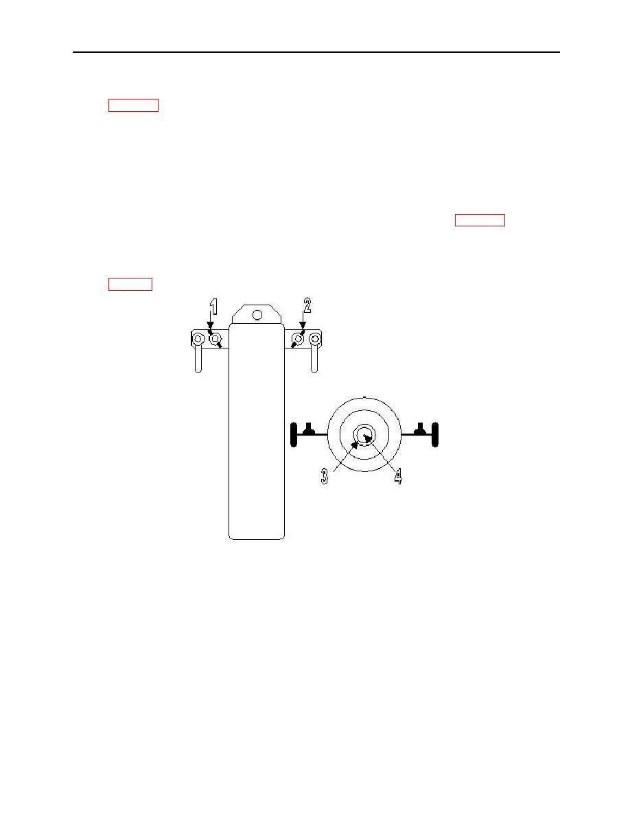
4. Locate the two elements that have the white band marked "3" along with the element marked with a "1"
5. Check continuity from the metal clip on the element marked "1" to one of the elements marked "3". The
resistance should be 1640 Ohms. Record the reading.
6. Repeat this procedure with the remaining element marked "3". Record the reading.
7. Repeat this procedure with the elements on the other side of the balun.
8. If the resistance readings are not 1568 to 1722 ohms then you need to perform the next procedure. If
the readings are within 1568 to 1722 ohms then skip the next step.
9. With the ends still disconnected from the balun, check the appropriate resistors (see fig. 2) in the failed
legs. Check resistance across the resistor terminals with the wing nuts on them using an ohmmeter.
They should read 779 to 861ohms. If they are not within spec, replace the resistor that is not within
specification then perform step 3 again.
10. Make the following resistance readings on the balun using an ohmmeter set to the lowest range (See
11. From point 1 to point 2: 1 to 2 ohms or less.
12. From point 1 to point 3: 1 to 2 ohms or less.
13. From point 1 to point 4: 1 to 2 ohms or less.
14. From point 2 to point 3: 1 to 2 ohms or less.
15. From point 2 to point 4: 1 to 2 ohms or less.
16. From point 3 to point 4: 1 to 2 ohms or less.
17. Disconnect both of the coaxial cables from the balun, the lightning arrestor, and the radio set.
18. Make the following resistance checks on the cables
19. From the center conductor to the center conductor on the other end of the cable: 0 to 1 ohm or less (use
lowest ohm scale).
1-28


 Previous Page
