CE-1008
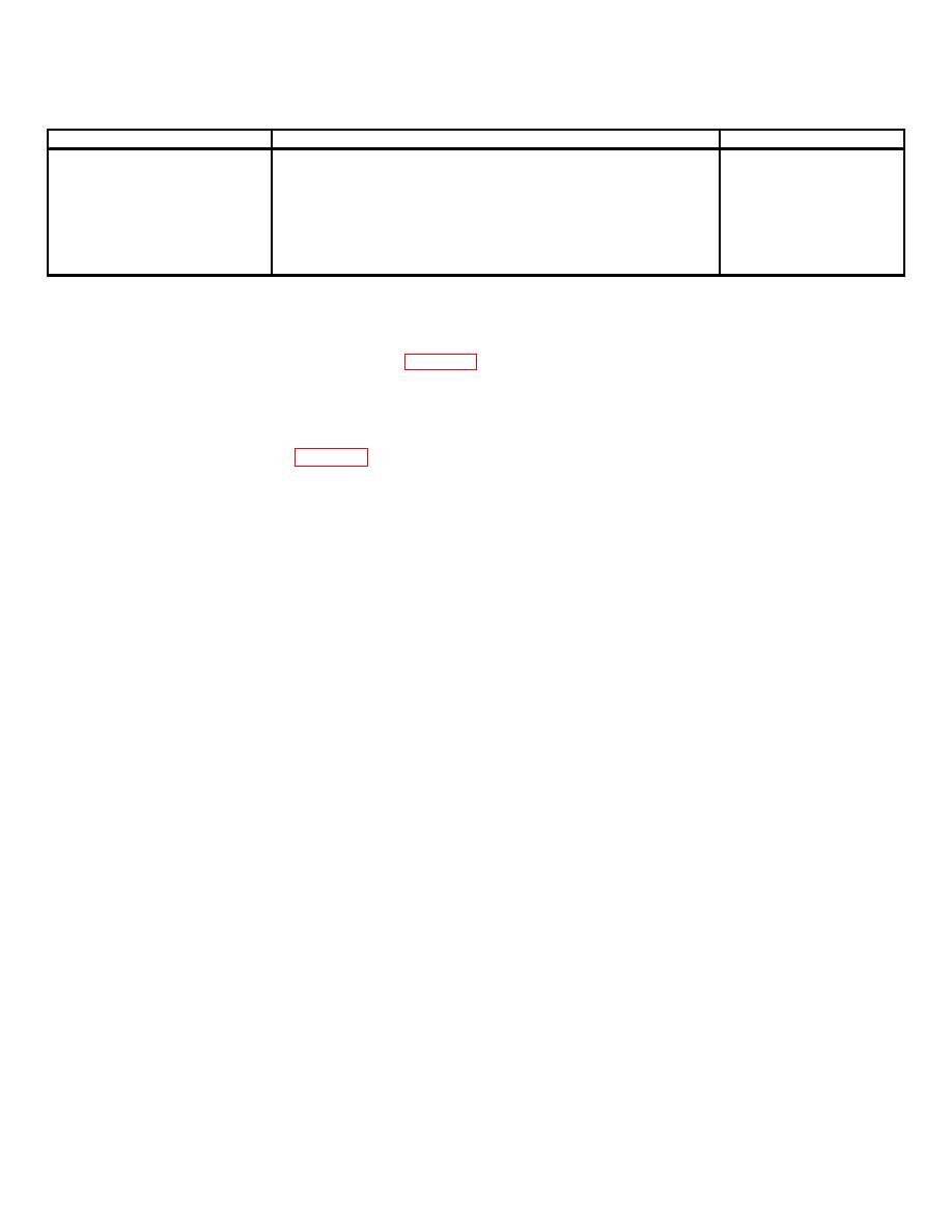
TABLE 4-1. PERIODIC INSPECTION AND PREVENTIVE MAINTENANCE SCHEDULE (CONT)
Component
Check
Schedule
All
a. Visually inspect all component parts.
Yearly
Replace if any component shows evidence of damage.
b. Lubricate the azimuth and elevation drive gear train with
a thin coat of MIL-G-3278A grease.
c. Check the radome, tower, and antenna.
3. TOOL REQUIREMENT
A. No special tools, other than those listed in Table 1-3, are required for inspection and routine maintenance of the
equipment. It is assumed that a set of standard hand tools are available on site.
4. TROUBLE ANALYSIS
A. The trouble analysis chart, Table 4-2, is designed to enable maintenance personnel to rapidly isolate the cause of
trouble to a specific circuit. Once located, normal troubleshooting procedures may be used to isolate the faulty
component. The most important step in the rapid location of trouble is the application of common sense. Prior to starting
a troubleshooting procedure to locate a trouble, all fuses and switch and control settings should be checked.
B. Since the equipment is primarily electromechanical, most major troubles may be isolated rapidly by observing
the following:
(1) If the system will operate in the local and slave mode, but not in the sector scan mode, the trouble is
probably in the scan generator circuit card. This should be replaced if this trouble occurs.
(2) If the system will not slew in azimuth, the trouble is probably servo-amplifier AR1 in the pedestal.
(3) If the system will not slew in elevation, the trouble is probably in elevation servo-amplifier AR2 in the
pedestal.
4-3


 Previous Page
