
TM 11-6625-1702-12
1 - 6 . I t e m C o mp r i s i n g a n O p e r a b l e E q u i p m e n t
panel is protected by a dust cover in addition to
the carrying case. The AN/ARM-115 contains a
0- to 500-millivolt (mv) power supply, one meter-
i n g circuit, one tuning indication circuit, and
switching and control circuits required to test
and align the 437S-l/lA antenna. All electrical
connections to the unit under test, to associated
t e s t equipment, and to the power source are
m a d e through plugs and jacks on the control
p a n e l . The control panel also contains three
s w i t c h e s , one control, one microammeter, and
one indicator lamp.
2642/ARM-115
Test Set, Antenna TS-2642/ARM-115 (fig. 1-1)
AN/ARM-115
c o n t a i n s controls, indicators, and connectors
that are used in performing operational checks
Test Set, Antenna AN/ARM-115 (fig. 1-1) is port-
of the 437S-1/lA antenna. All these items are on
able and can be used wherever 27.5 volts direct-
the test set front panel. The test set is usually
current (dc) is available. It is designed for use on
removed from the test set case for normal opera-
a workbench and can be easily transported in its
tion.
carrying case for use in the field.
A handle for carrying the AN/ARM-115 is pro-
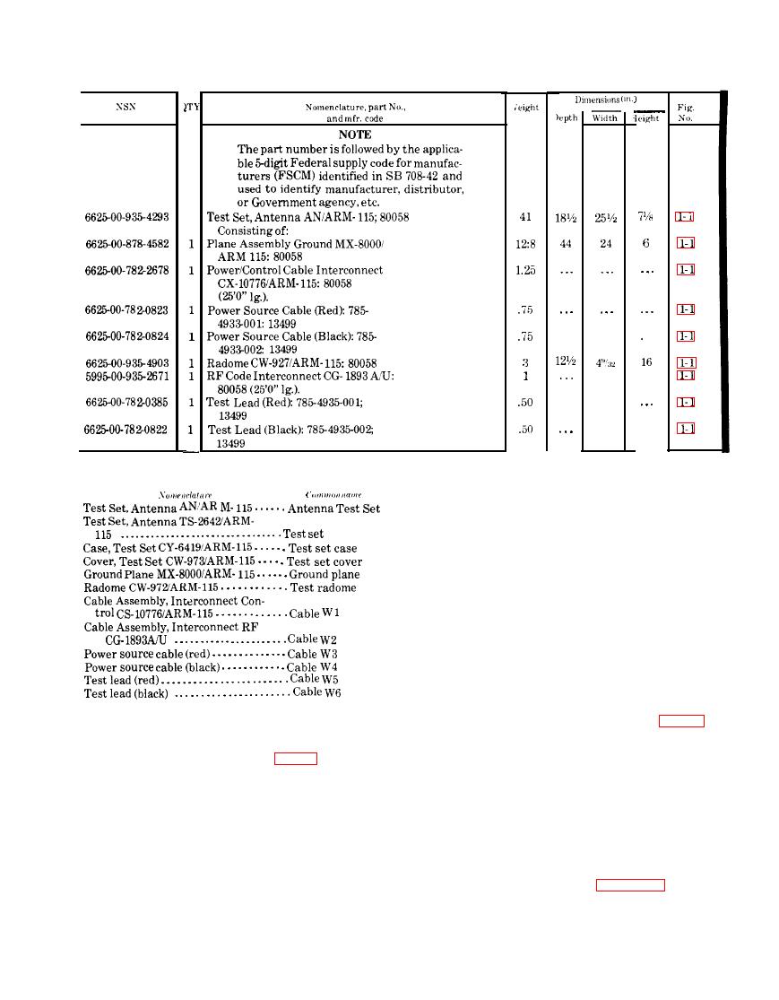
T h e minor assemblies of Test Set, Antenna
vided on the carrying case. The portion of the
AN/ARM-115 are included in figure 1-1. Special
AN/ARM-115 extending behind the control
Change 3

 Previous Page
