
TM 11-5985-379-14&P
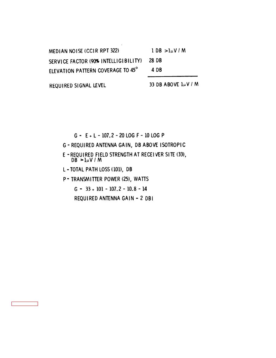
Required Signal Level.
Figure 3-8.
F i g u r e 3-9. Required Antenna Gain.
the dipole elements at a height of 15 feet. The
additional advantage of the sloping dipole con-
coaxial mast consists of eight identical sections,
f i g u r a t i o n is the vertically polarized component
(a figure eight-type radiation pattern) produced at
a n d i s c o n s t r u c t e d o f a l u m i n u m . T h e inner
the low frequencies that permits compatibility with
c o n d u c t o r of the coaxial mast is held concen-
trically within the outer conductor with a poly-
whip antennas where propagation conditions per-
u r e t h a n e f o a m . B a y o n e t - t y p e joints allow the
mit.
mast sections to be joined together quickly and
In order to provide an acceptable impedance to the
positively.
tuner of the AN/PRC-47, it is necessary to make
the sloping dipole fat. This is done by using two
T h e dipole radiating elements consist of four
wires positioned at right angles to one another.
wires for each half of the dipole. The four wires
They slope down to the earth and are made of
are equally spaced about the mast and serve as
flexible phosphor bronze wire with short lengths
guys as well as radiators.
of nylon rope attached to the ends through insula-
tors. Two of the elements are connected to the
inner conductor of the coaxial mast and the other
637K-1) and depicts the design of the mast,
two are connected to the outer conductor.
f e e d , insulators, a n d ground stakes. The mast
a l s o serves as the transmission line, feeding
3-8

 Previous Page
