
TM 11-5985-379-14&P
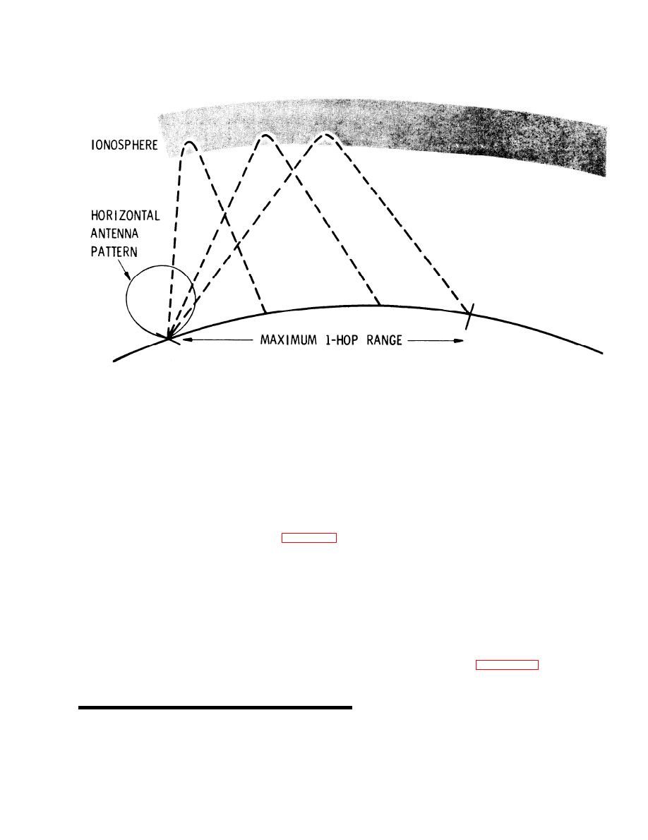
Horizontal Antenna Mounted for Short-Range Sky Wave.
Figure 3-4.
the direction off the dipole or wire ends. Due to the
The required antenna gain is computed to provide
p r o x i m i t y of the antenna to ground, this latter
a given field strength at a receiver site from the
mode radiates like a lossy transmission line and
t o t a l propagation path loss, the operating fre-
i t s efficiency is generally poorer than a whip.
quency, and the transmitter power. The total path
loss is found to be 101 dB (NBS Report 72491).
T h e shape of the radiation pattern of the hori-
The power delivered to the antenna by the AN/
zontal dipole is essentially constant for heights
PRC-47 is assumed to be 25 watts, taking into
n o t exceeding one-quarter wavelength, The dir-
account coupler losses. The equation for computing
ective gain of these horizontal antennas is 7 dB
the required antenna gain is shown in figure 3-9.
above an isotropic. Half-power beamwidths of the
T h e gain is 2 dB above an isotropic radiator.
v e r t i c a l l y radiated lobe are 80 degrees in the
plane of the dipole and 100 degrees in the plane
T h e required effective height of the antenna is
normal to the dipole axis.
found by considering the following.
For a fixed height above ground, the amount of the
W h e n a horizontal antenna is close to ground,
input power radiated proportionately in each of
e n e r g y is radiated in two modes. The desired
these modes is a function of the relative percentage
dipole mode produces radiation with a maximum
of the antenna input resistance characterizing each
in the vertical direction. The undesirable Bever-
mode. Each of these, in turn, is a function of the
age mode creates a vertical electric field between
height above ground. Figure 3-10 shows the total
t h e conductor and ground, producing vertically
input resistance and that portion due to the dipole
polarized ground-wave signal with a maximum in
mode as the dipole height is varied. As the height
l
Haydon, G. W., Lucas, D. L., and Harrison, R. A., "Technical Considerations in the Selection of
Optimum Frequencies for High Frequency Skywave Communication Services," p. 45, NBS Report 7249,
U. S. Dept. of Commerce, Boulder, Colorado.
3-5

 Previous Page
