
TM 11-5985-355-13
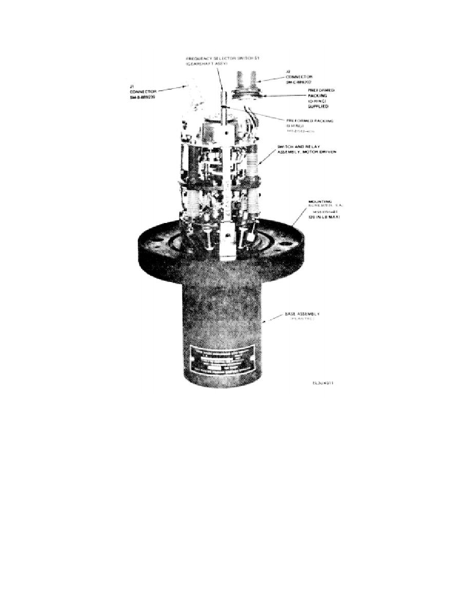
Figure 6-4. Matching Unit-Base, MX-9146/GRC, case cover removed, parts location
.
(b) Connect the center conductor of rf
(a) Remove matching unit case (b(1) above.
coaxial cable to center terminal of J1 connector
(b) Tag an(d unsolder eight wires from J2
connector (S.M-C-889202).
assembly.
(2) Replacement.
(c) Reassemble the MXS-9146/GRC as
(a)
Solder disconnected wires to J2
described in (b(2) above).
connector (SM-C-889202).
e. J2 Connector .4.ssetibly (fig. 6-4 and FO-1).
(1) Removal.
Change 2 6-6

 Previous Page
