TM 11-5985-362-13
3-6. REMOVAL AND INSTALLATION
Refer to Chapter 2 for removal and installation procedures.
3-7. DISASSEMBLY AND ASSEMBLY
Refer to Chapter 2 for disassembly and assembly procedures.
3-8. REPAIR
Operator and/or crew repair of the antenna is limited to replacement of damaged or defective components such as
WIRES or TOWER SECTIONS. Broken CERAMIC INSULATORS on DROP WIRES of the RIGHT, LEFT, and
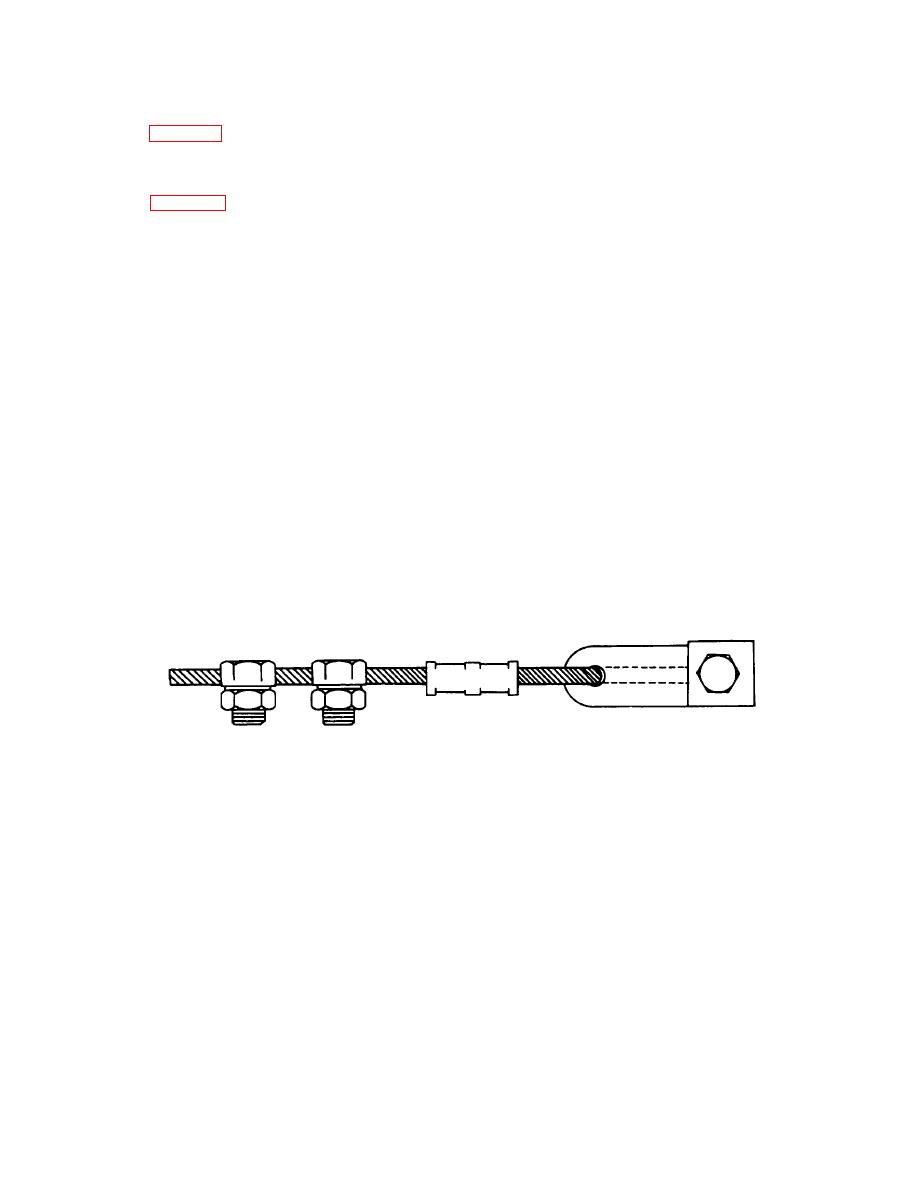
VERTICAL CATENARIES can be repaired by replacement using INSULATOR/WIRE REPAIR ASSEMBLIES 173-WIR-
01A or 173-WIR-02A. Repair of LAYOUT. WIRES or the MAIN and VERTICAL RADIATORS can be accomplished
using WIRE REPAIR PARTS KIT 245-WIR-01T contained as part of start up spares.
Replacement of Broken Insulator on Catenary Dropwires
a. Identify DROPWIRE size to broken insulator as either 1/16or 5/32-inch diameter and select appropriate
repair assembly.
b. Extend damaged or broken DROPWIRE-INSULATOR assembly on ground to determine original length.
c. Place the appropriate REPAIR ASSEMBLY next to damaged DROPWIRE-INSULATOR assembly and
clamp REPAIR ASSEMBLY into place with clamps provided maintaining original length within + 1/2-inch
(13 mm).
d. Cut damaged INSULATOR and unnecessary DROPWIRE away.
WIRES and INSULATORS should be as clean as possible for optimum antenna performance. hen necessary, clean
antenna components with water. If cleaned immediately before packing in transit cases, wipe down ANTENNA
COUPLER with clean dry cloth or allow to air dry prior to placement in case.
3-6


 Previous Page
