Home
Download PDF
Order CD-ROM
Order in Print
Home
>
Antennas, tv antennas, cb antennas, uhf antennas, reference and training manuals
>
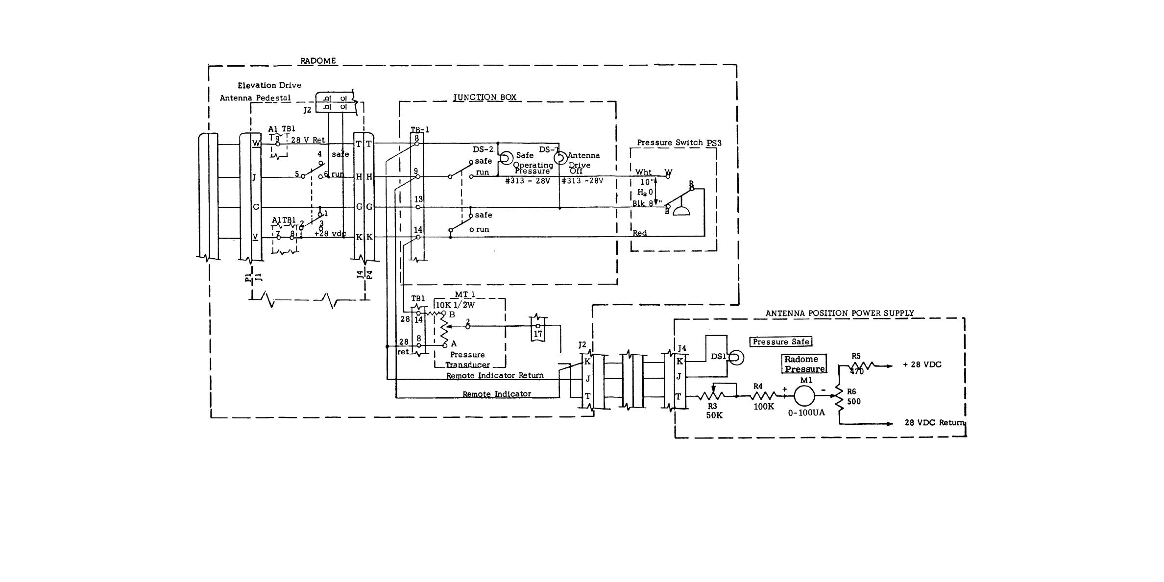
> Figure 1-9. Randome-Platform Pressure Safety Switch and Indicator Circuits, Simplified Schematic Diagram.
Figure 1-8. Radome-Platform Blower and Control Circuits, Simplified Schematic Diagram.
DEICER CIRCUITS
TM-32-5985-200-15 Antenna System QRC-280 (A) Manual
Page Navigation
20
21
22
23
24
25
26
27
28
29
30
CE-1008
12648
009
736357
Figure
1-9.
Randome-Platform
Pressure
Safety
Switch
and
Indicator
Circuits,
Simplified
Schematic
Diagram.
1-29/1-30


 Previous Page
