
TM 11-6625-1702-35
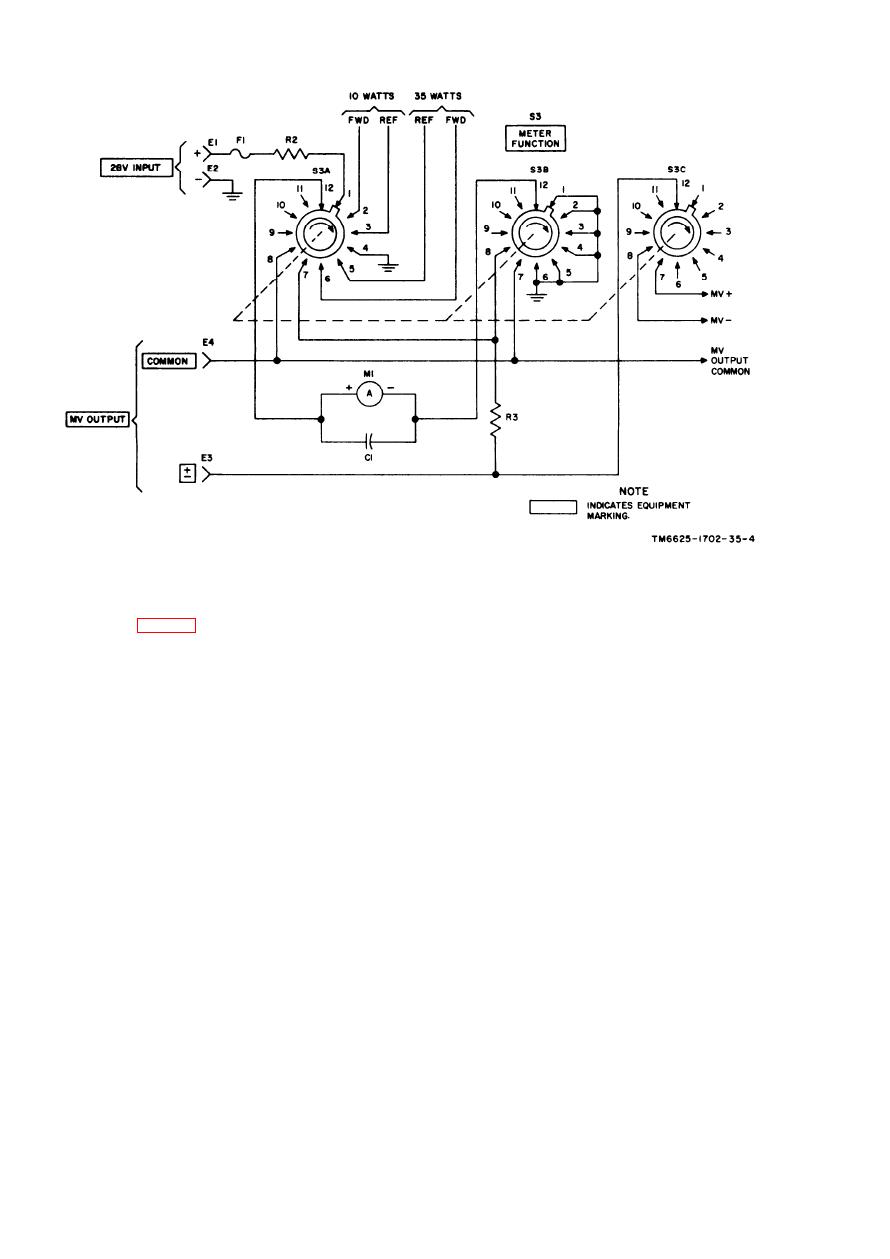
Figure 1-4. Meter circuit, schematic diagram.
1-12. Tune Indicator Circuit
charged, C2 will discharge to a lower level.
If this discharging process continues, C2 will
W h e n tuning of the antenna under test is
discharge to a level where the voltage applied
activated, negative pulses are supplied by the
across CR4, CR3, and the base-emitter junction
a n t e n n a under test to the base of Q1 and
of Q2 will cause Q2 to bias off. When Q2 biases
Q1 biases off. When Q1 biases off, C2 starts
o f f , Q3 conducts and DS1 lights, indicating
to discharge. As the negative pulse at Q1 re-
that tuning is in process. Under normal con-
turns positive, Q1 conducts and C2 charges.
ditions with +28 volts dc applied and no
If the time elapsed between pulses is too great,
input at pin K (coupler not connected) of
C2 will have charged and the process will start
the test set, DS1 will be lighted. In this man-
over again; however, if C2 is discharged and
ner DS1 also serves as a +28-volt de power
another pulse is received before C2 has
indicator for the test set.
1-6


 Previous Page
