
TM 11-5985-355-13
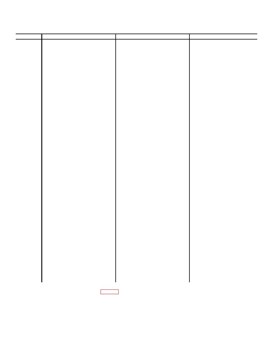
Table 4-2. Organizational Maintenance Troubleshooting Chart
Item No.
Trouble symptom
Probable trouble
Corrective measure
1
Antenna Element AS-2732/GRC
Defective AS-2732/GRC.
Replace AS-2732/GRC.
Is damaged.
a.
a.
2.
Receiver-transmitter power
Defective r/t control cable
Disconnect rf and control
supply fuse blows on any AS-
NOTE
(CX-13044/GRC) cables at
2731/GRC selector switch
Do not turn on trans-
r/t end of cables.
Position, or when a new
mitter when the AS-2371/GRC
(1) If fuse blows, replace
subband is selected
is disconnected from R/T unit.
r/t unit control cable.
b.
Defective Cx-13055/GRC
(2) If fuse does not blow,
Go to b below.
cable.
c.
b.
Defective rf cable.
Connect control cable
d.
Defective MX-9146/GRC
(CX-13055/GRC) to r/t
control cable, and
disconnect at J2
connector. If fuse
blows, replace cable
(CX-13055/GRC)
c.
If fuse does not blow,
replace rf cable.
d.
Replace MS-9146/GRC.
a.
a.
Defective control cable
Verify that the MX-9146/
3
MX-9146/GRC tunes to BAND 1 or
BAND 2, but not to both.
CX-13055/GRC or CX-4722(*)/
GRC rotary solenoid is
VRC.
Heard operating and
indexing by changing
BAND switch and MHz
control or manually
change frequency select-
or S1 to a number of freq-
uencies at least 10 MHz
apart. If rotary solenoid
operates in manual, but
not in auto mode, go to b
below.
b.
Replace control Adapter
Cable CX-13055/GRC or
CX-4722(*)/VRC, in turn.
c.
c.
Defective MX-9146/GRC.
If rotary solenoid does not
turn, replace MX-9146/
GRC with one known to
be good.
d.
d.
Defective r/t unit.
If rotary solenoid does not
turn, associated r/t unit is
defective.
4
MX-9146/GRC cycles continously
Defective MX-9146/GRC.
Replace MX-9146/GRC.
when new frequency is select-
ed.
a.
a.
5
Weak or no transmission/recep-
Defective MS-9146/GRC.
Remove AS-2732/GRC
tion on associated receiver
and perform continuity
or forward or reflected power
checks between J1 (rf
indications of AN/URM-182
input) and J3 (rf output)
exceed specified limits.
For each position of
selector switch S1. In
positions 42-47.5, 47.5-53,
53-56, 56-60, and 60-65,
resistance should be
approximately zero. If
not, replace MX-9146/GRC
NOTE
Insure that contact on top
of MX-9146/GRC pro-
trudes fully and is secur-
ed by setscrews and cap-
screw (fig. 2-2).
b.
b.
Defective AS-2732/GRC.
Check performance of AS-
2732/GRC using pro-
cedures in item No. 8,
table 4-1.
AS-2732/GRC and cable mount assembly.
(2)
Remove contact (SM-B-542008) with
(2) Remove the AS-2732/GRC from cable
two screws.
mount assembly by turning the AS-2732/GRC
(3) Remove ring (SM-B-889201)with
counterclockwise.
screwdriver.
(3) To replace the AS-27.32/GRC, apply
(4) Remove contact (SM-B-542007) from
silicone compound (item 3, app E) on O-ring (MS9068-
insert (SM-B-542004).
213) and threaded portion of cable mount, and replace
(5) Replace contact (SM-B-542007), insert
the new AS-2732/GRC to cable mount assembly.
(SM-B-542004), and ring (SNI-B-889201).
(4) Install the safety lock wire (para 2-3f).
(6) Replace contact (SM-B-542008) with
b. Spring Contacts (fig. 6-1).
two screws. Apply 1 to 2 (drops of sealant (item 8 or
(1) Perform the AS-2732/GRC removal
8A, app E).
procedures above (a (1) and (2) above).
Change 2 4-3


 Previous Page
