
TM 11-5985-355-13
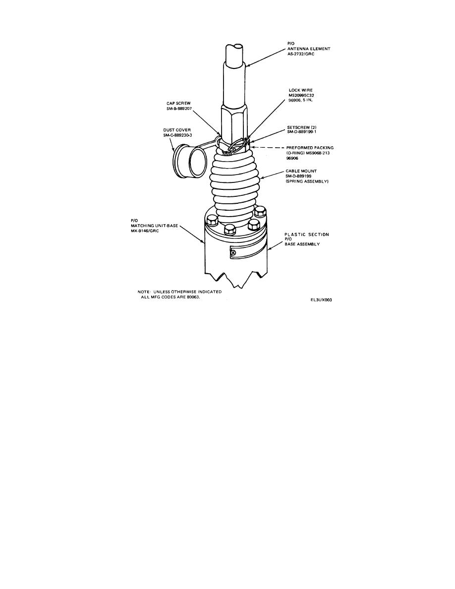
Figure 2-2. Antenna AS-2731/GRC partial view, parts location
between MX-9146/GRC threaded stud and the antenna
9146/GRC unit is not aligned with the
mounting bracket per type of setup (fig. 2-4).
frequency radio setting, and the rt unit is
i. Connect control cable assembly CX-13055/GRC
on, arcing may occur which will result in
to J2 connector of NIX-9146/GRC.
burnt connector pins.
i. Connect control cable from the associated rt unit
CAUTION
to free end of CX-13055/GRC connector.
Before connecting CX-13055/GRC to
k. Connect the rf cable from the associated radio
control cable of radio rt unit, be sure
to connector J1 of MX-9146/GRC (fig. 2-5).
your radio rt unit is turned off. If the MX-
2-3


 Previous Page
